Introduction
This project is to create an Enigma Machine simulation.
The document is my first pass through a design. The as-build (code) is somewhat different. (See the other documents.)
Program #1
Create rotor configurations and write them to a file. In order to share them, the configuration file format is standardized and will
- contain eight rotors (I, II, III, IV, V, VI, VII, VIII)
- each rotor with have 26 letters
- each rotor's internal wiring will be randomly generated
- The configuration file will contain csv data
- each line will have the following format:
Rotor,input letter,output letter
for example
I,A,X
I,B,D
...
...
II,A,Q
II,B,U
...
...
Note:
Program #2
Simulate an enigma machine, and only use rotors.
- read a rotor configuration file
- allow the user to select which rotors to use
- allow the user to select which position to place each rotor (left, middle, right)
- allow the user to select the starting position for each rotor
- allow the user to entering text to be encrypted
- allow the user to enter text to be decrypted
- limit the amount of text to be entered at one time to (60 characters?)
- on request, display the internal state of the simulation
Programs #3 and #4
This will be the same as program #1 and #2, with the plugboard added.
Allow the user to configure the plugboard. (interactive?) (add to rotor configuration file?) (separate configuration file?)
Program #5
Create a GUI for the simulation.
Enigma Machine Simulation Design
Rotor
- there will be 8 rotors available
- each rotor has a different wiring
- each rotor will have 26 letters (all caps)
- the rotors will be numbered (named) I, II, III, IV, V, VI, VII, VIII
- the rotor wiring will be in a data file and read by the simulation
- Each rotor supports starting on any letter
- The simulation will use 3 rotors
- every time there is a keypress, the right rotor is advanced one position. After a complete rotation, the middle rotor will be advanced one position. it is the same for the left rotor. when the middle rotor makes a complete rotation, the left rotor is advanced one position.
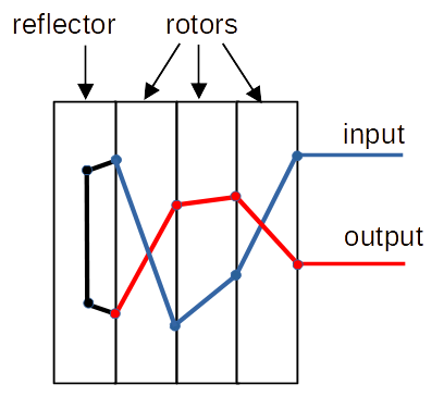
- the data input flow is to the
- right rotor, then to the
- middle rotor, then to the
- left rotor, then to the
- reflector, and back to the
- left rotor, then to the
- middle rotor, then to the
- right rotor, then to the
- data display